What Are Bevel Gears and What Types Are Available?
Bevel Gears are conical-toothed components designed to transmit motion between intersecting or offset shafts. They often appear inside automotive differentials, right-angle drives, machine tools, and compact industrial gearboxes. Their tapered teeth change rotational direction, usually by 90 degrees, while carrying torque through a carefully controlled contact pattern.
Dr. Hermann J. Stadtfeld, a respected bevel-gear researcher and engineer, has emphasized a practical principle: “Bevel gears are a system, not merely a set of teeth.” That observation matters during design. A small error in mounting distance, tooth alignment, lubrication, or backlash can create noise, heat, and premature wear. The drawing may look perfect. The assembly may still fail.
This guide examines the main types of Bevel Gears, including straight, spiral, zerol, and hypoid designs. Straight bevel gears are relatively simple and economical, but they can produce noticeable impact noise at higher speeds. Spiral bevel gears provide smoother engagement because several tooth sections share the load. Zerol gears offer a compromise, while hypoid gears support offset shafts and are common in vehicle final drives. Each type has a different manufacturing cost, load capacity, and maintenance demand.
A neat classification can mislead.
Real performance depends on more than tooth shape. Engineers must consider speed, torque, shaft geometry, materials, heat treatment, lubrication, and operating temperature. In practice, even experienced teams revisit their assumptions after testing. That humility is useful. A bevel gear that performs well in a model may behave differently under vibration, contamination, or repeated shock loads.
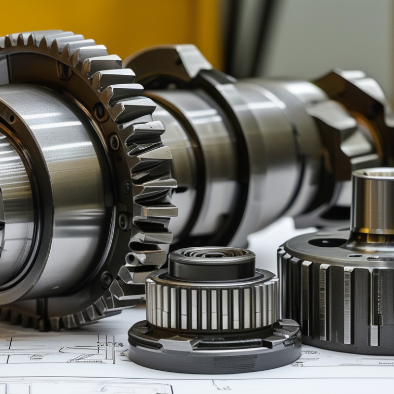
What Are Bevel Gears and How Do They Work?
Bevel gears transmit rotary motion between intersecting shafts, often at a 90-degree angle. Their conical tooth surfaces change the direction of torque while maintaining controlled speed. As the smaller pinion turns, its teeth push against the larger gear’s teeth. This contact creates rotation around a different axis. Gear ratio determines whether the output shaft turns faster, slower, or with greater torque.
Tooth geometry strongly affects performance. Straight bevel gears have simple, radial teeth and suit moderate speeds. Spiral bevel gears use curved teeth, producing smoother engagement and lower vibration. However, their sliding action can increase heat and lubrication demands. Zerol bevel gears offer a compromise between straight and spiral designs. Hypoid gears use offset shafts and provide quiet operation, but they need carefully selected lubricant and precise alignment.
In practical assembly, backlash must be measured rather than guessed. A technician may rotate the shaft gently and check movement with a dial indicator. Too little clearance can cause heat, noise, and premature wear. Too much clearance can create impact loads. Small errors matter. Mounting distance, tooth contact, housing stiffness, and lubrication all influence service life. I have found that visual inspection alone can miss a narrow contact pattern near the tooth edge. Load testing can reveal problems that appear harmless during hand rotation. Even accurate calculations need real-world verification.
What Are Bevel Gears and What Types Are Available?
Bevel gears transmit motion between intersecting or offset shafts. Straight, spiral, and Zerol bevel gears are commonly arranged at a nominal 90° shaft angle, while hypoid gears use offset, non-intersecting shafts.
How they work: Mating conical gears transfer torque while changing the direction of rotation. Straight bevel gears use straight teeth, spiral bevel gears use curved teeth for smoother engagement, Zerol gears have near-zero spiral angle, and hypoid gears combine curved teeth with shaft offset.
Comparing Common Bevel Gear Types and Their Uses
What Are Bevel Gears and What Types Are Available?
Bevel gears transmit motion between intersecting or offset shafts, often at a 90-degree angle. Their conical teeth change both speed and direction. Straight bevel gears use simple, radial teeth. They suit low-speed machinery, compact drives, and applications where cost matters. However, their tooth engagement can create noticeable noise and vibration at higher speeds.
Spiral bevel gears have curved teeth that engage gradually. This design usually produces smoother rotation, greater load capacity, and quieter operation. It also creates axial thrust, so the housing and bearings must be selected carefully. Zerol bevel gears offer curved teeth with minimal spiral-angle effect. They can provide smoother running than straight gears while limiting axial forces. Miter gears are a special equal-ratio arrangement. They redirect motion without changing speed, making them useful in right-angle mechanisms.
Hypoid gears handle offset shafts rather than intersecting shafts. Their sliding contact supports compact layouts and high torque, but it demands accurate alignment and suitable extreme-pressure lubricant. In practical installations, tooth pattern checks matter as much as catalogue calculations. A clean contact mark near the tooth center usually indicates healthier load sharing. Small errors matter.
Choosing a bevel gear type depends on speed, torque, noise limits, space, lubrication, and maintenance access. A simple selection chart can mislead. I have seen a theoretically suitable gear fail because the housing flexed under load. Straight gears may be adequate, while spiral or hypoid gears often justify their extra complexity in demanding drives. Inspections should include backlash, tooth wear, bearing condition, and unusual temperature changes.
How to Select the Right Bevel Gear for an Application
Bevel gears transfer motion between intersecting shafts, often at a 90-degree angle. Their tapered teeth create a cone-shaped gear set. Common types include straight, spiral, zerol, and hypoid bevel gears. Each type changes noise, load capacity, efficiency, and manufacturing cost. Selecting the right bevel gear starts with the application, not the catalog picture.
Measure the required speed ratio, torque, shaft angle, and available space. A straight bevel gear may suit low-speed equipment with modest loads. Spiral bevel gears usually run more smoothly under higher loads, but they need accurate alignment and stronger support. Hypoid gears allow offset shafts, although sliding contact can increase heat and lubrication demands. Check starting torque, shock loading, operating hours, and expected service life.
In field inspections, poor mounting often causes more damage than incorrect tooth design. That detail is easy to overlook. Verify backlash, housing stiffness, bearing positions, and lubrication before final selection. A calculation can still miss real vibration or contamination.
Tips:
Match the gear material to the load and environment. Confirm the manufacturer’s rated torque at your actual speed. Keep the shaft angle and mounting tolerances precise. If noise matters, test the gear under realistic load conditions. Do not choose by ratio alone. It is tempting, but incomplete. When requirements remain uncertain, compare two suitable designs and review their thermal, maintenance, and replacement implications.