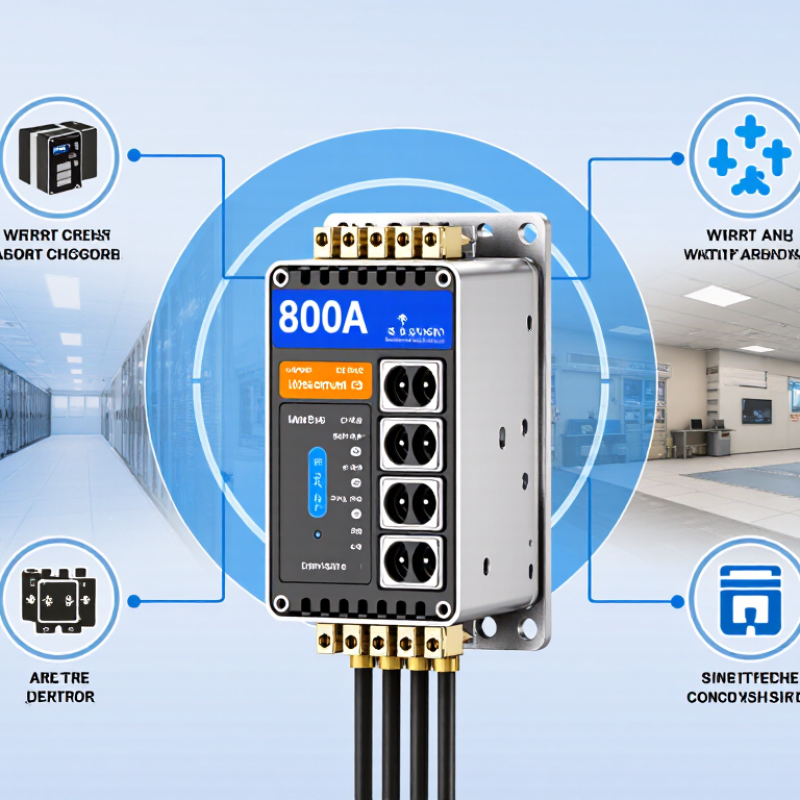
| Continuous current rating | 800 A
Designed for continuous loads up to the marked ampere rating when installed under the specified conditions. | The transfer mechanism carries the connected load from the selected source through the main contacts. | Confirm the 800 A rating, temperature-rise data, terminal capacity, and enclosure configuration. | The switch rating must not be lower than the calculated continuous and non-continuous load requirements. |
| System voltage | Common low-voltage configurations include 208Y/120 V, 480Y/277 V, and 600Y/347 V, depending on the market. | The controller monitors source voltage and frequency within programmed pickup and dropout limits. | Request the exact voltage, frequency, phase, neutral, and short-circuit rating for the intended installation. | Voltage and system grounding arrangement must match the ATS nameplate and upstream protection. |
| Phase and pole configuration | Three-phase, 3-pole or 4-pole designs are common. A 4-pole design switches the neutral. | All designated phase conductors, and the neutral where applicable, are transferred by an mechanically or electrically interlocked mechanism. | Verify whether the neutral is solid, switched, overlapping, or separately derived according to the system design. | Neutral switching depends on grounding, bonding, generator, and jurisdictional requirements; it is not interchangeable in every installation. |
| Source arrangement | Two-source system: normal utility source and standby generator or alternate source. | After detecting an acceptable alternate source, the controller commands the transfer from normal to emergency. | Check compatibility with utility feeds, generator output, bypass-isolation equipment, and remote control interfaces. | Source protection, phase rotation, and available fault current must be coordinated with the complete power system. |
| Normal-source sensing | Voltage, frequency, phase loss, phase sequence, and sometimes voltage imbalance are monitored. | If the normal source falls outside the programmed limits for the time-delay period, the controller initiates the emergency sequence. | Confirm adjustable pickup, dropout, undervoltage, overvoltage, frequency, and time-delay settings. | Sensing thresholds should prevent nuisance transfers caused by short-duration disturbances. |
| Engine-start signal | Normally open or normally closed dry-contact output, commonly used to start a generator. | When the normal source is unacceptable, the ATS sends a start command and waits for the alternate source to stabilize. | Verify contact rating, programmable start delay, remote-start compatibility, and fail-safe behavior. | Generator controls must be configured so that the start circuit remains compatible with the ATS control logic. |
| Engine-start delay | Adjustable delay is commonly provided to avoid starting the generator for momentary utility disturbances. | The controller waits through the programmed delay before issuing the generator-start command. | Confirm the available adjustment range and whether separate delays are provided for start, transfer, retransfer, and cooldown. | Delay settings should reflect generator starting time, critical-load requirements, and the emergency power design. |
| Emergency-source acceptance | Acceptance is based on configured voltage, frequency, phase sequence, and stability limits. | After the alternate source reaches acceptable conditions, the controller permits transfer. | Verify source-available indication, stabilization delay, phase-sequence protection, and test functions. | The ATS should not transfer a load to an unstable or incorrectly phased source. |
| Transfer method | Most open-transition systems use break-before-make switching. | The normal contacts open before the emergency contacts close, preventing the two sources from being connected together. | Confirm open-transition, closed-transition, or delayed-transition construction and the applicable transfer rating. | Closed-transition operation requires specific power-system coordination and may require additional utility approval. |
| Transfer time | Mechanical transfer time is product-specific; total time also includes sensing, generator start, and source stabilization delays. | The controller energizes the transfer mechanism after the alternate source is accepted. | Request measured transfer-time data, contactor or circuit-breaker technology, and load-type limitations. | Do not treat the mechanical transfer time as the total outage duration experienced by the load. |
| Retransfer to normal source | Adjustable retransfer delay is commonly used after utility power returns. | Once the normal source remains acceptable for the programmed period, the ATS returns the load to normal power. | Check retransfer delay, emergency-source cooldown, return-to-normal test, and manual retransfer options. | A cooldown period allows the generator to run unloaded before shutdown, reducing thermal stress. |
| Manual and automatic controls | Typical functions include automatic, test, manual, and emergency override modes. | Automatic mode performs source monitoring and transfer logic; test mode simulates or initiates an emergency event. | Verify local controls, remote test input, lockout functions, password protection, and event logging. | Manual operation should include clear interlocking and procedures to prevent unsafe source paralleling. |
| Short-circuit and withstand rating | Common ratings vary by voltage, construction, upstream protection, and certification; no single value applies to every 800 A ATS. | The transfer equipment must withstand and interrupt fault conditions only within its marked rating and protection scheme. | Obtain the marked short-circuit current rating, test conditions, fuse or breaker requirements, and coordination data. | The available fault current at the installation must not exceed the marked rating of the complete assembly. |
| Load categories | May serve lighting, HVAC, pumps, fire and life-safety equipment, data systems, and other essential loads when properly rated. | The ATS transfers the connected load as a group unless the system uses multiple transfer switches or staged load control. | Confirm motor-load, transformer-inrush, capacitor, non-linear-load, and emergency-load performance. | Large motors and transformers can cause voltage dips or inrush that affect transfer performance. |
| Bypass-isolation option | Available on some 800 A assemblies for maintenance without interrupting critical loads. | Bypass equipment routes power around the ATS while isolation permits inspection or replacement of the switching section. | Verify bypass source selection, isolation procedure, interlocks, arc-flash labeling, and maintenance access. | Bypass-isolation construction increases equipment size and cost but can improve service continuity. |
| Environmental enclosure | Indoor and outdoor enclosures are available with different ingress, corrosion, ventilation, and temperature capabilities. | The controller and switching components operate within the permitted ambient and enclosure conditions. | Confirm enclosure type, ambient temperature range, altitude derating, humidity limits, seismic options, and heater requirements. | Outdoor installations may require weather protection, condensation control, and appropriate corrosion resistance. |
| Communications and monitoring | Optional dry contacts, metering, alarms, and serial or Ethernet-based communications may be available. | Status information such as source availability, switch position, alarms, and transfer events can be sent to a monitoring system. | Check protocol support, cybersecurity controls, time synchronization, event memory, and metering accuracy. | Communication features should not replace local visual indication and required hardwired emergency signals. |
| Standards and certification | Common references include UL 1008 in North America and IEC 60947-6-1 in applicable international installations. | The controller and switching assembly operate within the tested construction and certification scope. | Request certificates, test reports, installation instructions, and country-specific approval documentation. | NFPA 110, NEC requirements, and local electrical regulations may apply to emergency and standby power systems. |
| Maintenance and lifecycle support | Maintenance typically includes inspection, cleaning, connection checks, operational testing, and review of event logs. | Periodic testing verifies sensing, transfer, retransfer, alarms, generator start, and mechanical operation. | Evaluate spare-parts availability, service documentation, commissioning support, training, and warranty terms. | Maintenance intervals must follow the manufacturer’s instructions, operating environment, and facility risk assessment. |
| Supplier selection priority | Best-fit supplier: technically compliant, properly certified, serviceable, and capable of delivering the required configuration. | A reliable ATS depends on correct sizing, settings, installation, commissioning, and coordinated protection—not only the nominal 800 A rating. | Compare documented test evidence, engineering support, lead time, customization, service coverage, and total ownership cost. | Use a project-specific compliance matrix before purchase; do not select solely on price or advertised transfer speed. |